Examples
VHDL
Lets Look at the following VHDL:
library ieee;
use ieee.std_logic_1164.all;
use ieee.numeric_std.all;

entity vhdl_sm is
    port (
        clk   : in std_logic;
        reset : in std_logic;

    );
end entity vhdl_sm;

architecture rtl of vhdl_sm is
type sm_t is (IDLE,PUSH_A,PUSH_B,CRC); --! My State machine
signal state : sm_t;
signal next_state : sm_t;

signal push_a_done;
signal push_b_done;
signal new_data;
signal crc_done;

begin

incr_sm_proc: process (clk,rstn)
begin
    if (rstn = '0') then
        state <= IDLE;
    elsif rising_edge(clk) then
       state <= next_state;
    end if;
end process;


sm_proc: process(all)
begin
    case state is
        when IDLE =>
            if (new_data = '1') then
                next_state <= PUSH_A;
            end if;
        when PUSH_A =>
            if (push_a_done='1') then
                next_state <= PUSH_B;
            elsif (push_a_done='1' and push_b_done='1') then
                next_state <= CRC;
            end if;
        when PUSH_B =>
            if (push_b_done='1') then
                next_state <= PUSH_A;
            end if;
        when CRC =>
            next_state <= IDLE;
        when others =>
            next_state <= IDLE;
    end case;
end process;
end architecture;
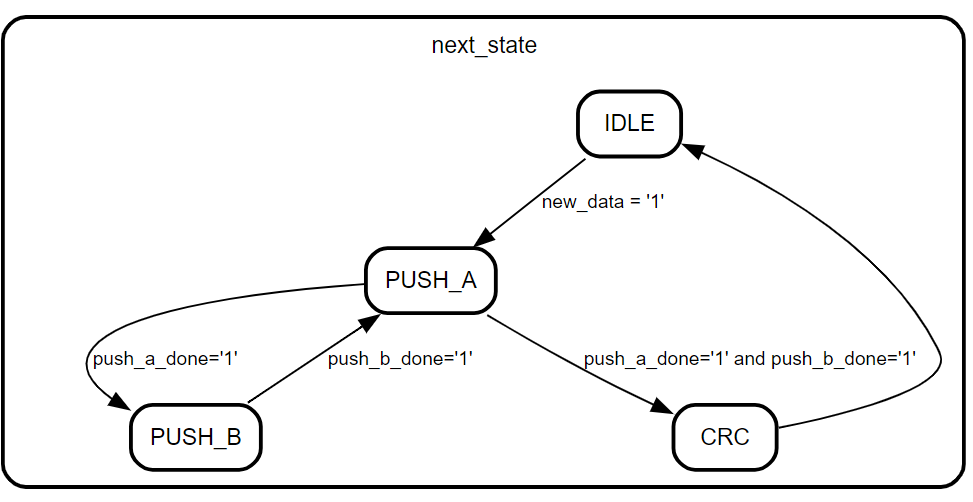
This will correspond with the following state machine diagram:
Image 1: State Machine In VHDL

Verilog
We can also do the same with verilog:
module verilog_sm (
    input clk,
    input rstn
);

wire push_a_done;
wire push_b_done;
wire new_data;
wire crc_done;

typedef enum logic[1:0] {IDLE,PUSH_A,PUSH_B,CRC} state_t;
state_t state;
state_t nextstate;

always @(posedge clk or negedge rstn) begin
    if (~rstn) begin
        state <= IDLE;
    end
    else begin
        state <= nextstate;
    end
end

always_comb begin
    case (state)
        IDLE: if(new_data) nextstate = PUSH_A;
        PUSH_A: begin
            if(push_a_done) nextstate = PUSH_B;
            else if (push_a_done&push_b_done) nextstate = CRC;
        end
        PUSH_B: if(push_b_done) nextstate = PUSH_A;
        CRC: nextstate= IDLE;
        default: nextstate = state;
    endcase
end
endmodule
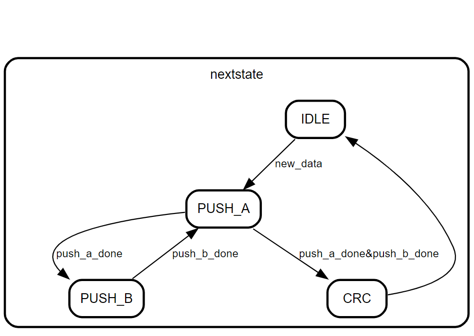
This will correspond with the following state machine diagram:
Image 2: State Machine In Verilog
